We need the screen to remain blank (black) while the RPi boots so the nasty linux scrolling text isn’t seen as it would look awful for the product we’re using it in (it needs to startup with a product splash screen image once the RPi is ready to display it). The backlight on the display control PCB is controlled by an atmel device but currently is just on from the moment it powers up. Here’s how to take control of it.
Raspberry Pi Touch Display (2022, 4.8)
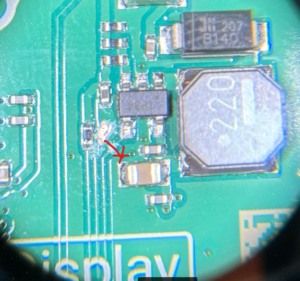
The components aren’t marked on this PCB silkscreen, so there are no component IDs to quote. The same modification is being made as for early versions though, however the IC is in a new position and they now have a new RPi microcontroller in place of the Atmel. Measuring the voltage on the pin, it is now only 1.9V, but that will be due to the new microcontroller. The IC is still powered at 5V and will therefore still be fine with our 3.3V signal on the pin when we want to turn the screen on.
Cut the track as shown an also scrape off an area of the solder resistor over the ground copper as shown:
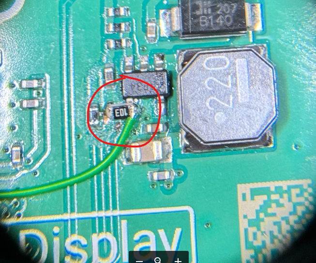
Use a bit of flux on the copper ground area and solder a 10K 0603 resistor from it to the IC pin, to act as a pull-down on powerup (this design has removed the pull-down present in previous designs, presumably because the new microcontroller has one or drives the line fast enough at power on).
Now connect the IC pin to a 3.3V IO pin of your own (one of the RPi IO pins is fine) using a wire.
That’s it, simply drive the signal high (+3V3) to turn the backlight on. With it low the screen appears totally black (as if off) and you can only see what it is doing if you shine a bright light at it.
Raspberry Pi Display V1.1
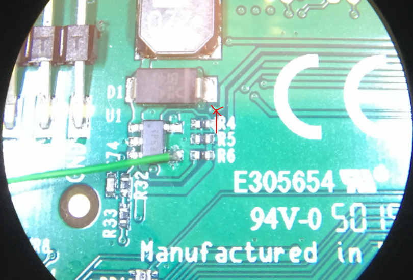
The IC U1 (device marking TP53 on our board) is driving the LCD backlight.
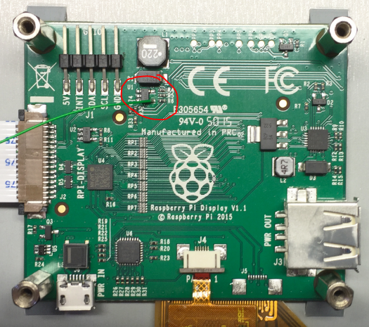
The resistor R4 pulls the signal down but the Atmel microcontroller is driving the signal high at +3.3V. To control the signal externally simply cut the track coming off R4 to the via next to it (the line with the ‘X’ below) to disconnect the Atmel signal. Now connect the U1 pin to a 3.3V IO pin of your own (one of the RPi IO pins is fine) using a wire.
That’s it, simply drive the signal high (+3V3) to turn the backlight on. With it low the screen appears totally black (as if off) and you can only see what it is doing if you shine a bright light at it.
Raspberry Pi Display V1.0
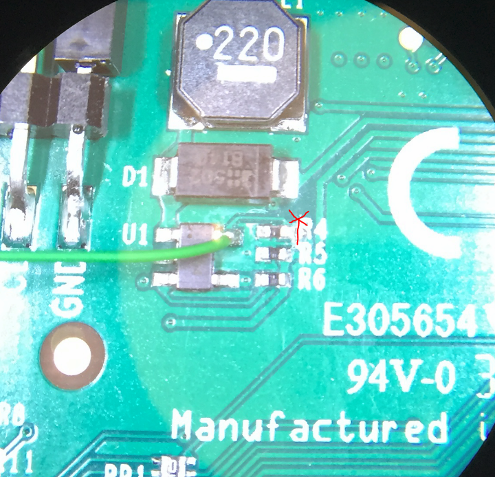
The IC U1 (device marking TP54 on our board) is driving the LCD backlight, by the looks of things constant current switch mode driving of it with a 1MHz frequency via L1 etc.
The resistor R4 pulls the signal down but the Atmel microcontroller is driving the signal high at +3.3V. To control the signal externally simply cut the track coming off R4 to the via next to it (the line with the ‘X’ below) to disconnect the Atmel signal. Now connect the U1 pin to a 3.3V IO pin of your own (one of the RPi IO pins is fine) using a wire.
That’s it, simply drive the signal high (+3V3) to turn the backlight on. With it low the screen appears totally black (as if off) and you can only see what it is doing if you shine a bright light at it.
We only need to turn it off during boot but if anyone is feeling like a trawl and discovers what device U1 is then please let us know in the comments below in case its handy for people who want to vary the brightness by using a PWM drive signal as its likely the IC will accept one but it would be good to know the recommended drive requirements. Hopefully a nice and simple software solution will appear from the RPi folks soon to avoid needing to do this, but for now it does the trick.