Note that we are not currently sure if the new pin 27-40 PWM1, GPCLK1 and GPCLK2 peripheral pin functions will be made accessible under Raspbian and if so which pins they will be assigned to, hence the duplicated pins shown with these functions.
Lost From The Model B Rev 2 Board
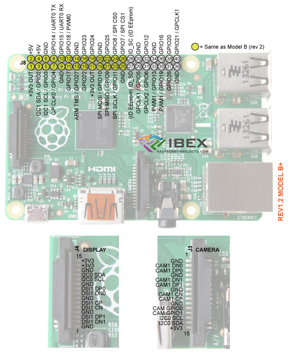
The P5 connector is not present on the new Model B+ board and its pins have not been moved to the new J8 connector,. This means the loss of the 2nd I2C port (although this peripheral is available via the display and camera FFC connectors – TBC if this is easy to enable for general use under Raspbian). The pins that are no longer present via a header are:
I2C0 SDA / GPIO28
I2C0 SCL / GPIO29
GPIO30
GPIO31
3.3V Output
External circuitry may draw up to a total of 50mA max current from the 3.3V Out pins (true for Model B so presumably true for Model B+ but not confirmed as full schematic not yet available).
Is maximum current from 3.3V pin really 50mA?
IO Pins
All IO pins are 3.3V, not 1.8V. Pins are not 5V tolerant.
Full details are available here
Max Current
Maximum 16mA per IO pin (sink or source) with the total current from all pins not exceeding 51mA (true for Model B so presumably true for Model B+ but not confirmed as full schematic not yet available). See a detailed explanation here.
Power-up State
Its likely all pins are set as inputs on power up (TBC).
I2C pins (e.g. Pj-3 and P8-5) are therefore high due to the pull up resistors on these pins.
Pull-Up & Pull-Down resistors
The GPIO ports include the ability to enable and disable internal pull-up or pull-down resistors from code.
Pull-up is 50K min – 65K max.
Pull-down is 50K min – 60K max.
I2C
1K8 pull up resistors are included on the RPi board so are not needed externally (true for Model B so presumably true for Model B+ but not confirmed as full schematic not yet available).
Interfacing the RPi 3.3V I2C pins to a 5V device like an Arduino – see here.
SPI
The Chip Select signals are for up to two independent slave devices. It seems that with the SPI port enabled in Raspbian both the CS0 and CS1 pins are assigned to it and therefore can't be used as IO (our assumption – correct?)
PWM Pin
The PWM pin available on the GPIO header is shared with the Audio system (true for Model B so presumably true for Model B+ – not confirmed as full schematic not yet available). This means that you can't use the PWM output and play audio through the 3.5mm jack at the same time.
3.3V / 5V Interfacing
See our other page here
ID_SD & ID_SC Pins
These are for an auto configuration eeprom which you can include on your RPi add on board and which Raspbian will read to detect the board connected. For more info see here.